Troubleshooting manual
Welcome to troubleshooting part of Viessmann Boilers Guide. Before starting any work on Viessmann boiler you should be aware working on any gas appliance without having proper qualifications (Gas Safe Registered) is prohibited by law. Electrical work on Viessmann equipment should be carried out by electricians and system should be commissioned by proper system installer or a qualified person authorized by the installer.
Safety first!
Working on gas appliance is a serious safety issue. You should never:
- smoke
- avoid flames and sparks
- turn on lights or appliances on/off
Attention! Life danger- when smelling the gas you should:
- close the shut off gas valve
- open doors and windows, let the fresh air in
- remove all people and animals from the danger zone
- inform your electricity and gas supplier
- shut down the electricity supply to the building till the issue is resolved
Escaping gas leak can lead to explosions which may result in serious injury! Flue gas can lead to life-threatening poisoning. Whenever you detect the flue gas you should
- turn off the heating system
- open doors and windows in order to ventilate the room
- close all doors to the room
When repairing the heating system remember to:
- close the main gas shut-off valve and safeguard against unauthorized reopening
- isolate the system from the power supply and re-check that it is no longer ‘live’
- protect the system against unauthorized re-connection.
Attention! Electronic modules can be damaged by electrostatic discharges. Touch earthed objects, such as heating or water pipes, to discharge static loads.
High limit safety cut-out
The high limit safety cut-out is part of the boiler. The high limit safety cut-out is located behind the boiler programming unit. Note that any high limit safety cut-out response requires a manual reset. This function gets started only when the flow temperature exceeds 100 °C.
On another hand this function can be terminated only once the flow temperature has dropped to minumum 70 °C.
If you don’t reset this function it will have direct effect on the boiler safety function and can result in system
damage.Whenever the high limit safety cut-out has been triggered, check that afterwards the thermally
activated safety valve is reset.
In order to perform high limit safety cut out follow steps below:
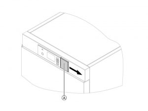
- Move cover A on the programming unit to the right
- Press the green button on the high limit safety cut out. A quiet “click” will be audible. The high limit safety cut-out has been reset.
- .Close cover A on the programming unit.
- Acknowledge excess temperature at the programming unit of the control unit with OK
Fault display
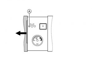
For weather-compensated control unit, whenever there is a fault, the red fault indicator A will illuminate on the display and the fault code will be displayed
The fault code is displayed with OK. Explanations of most codes are present in the tables below.For some faults, the type of fault is also displayed in plain text. Acknowledging a fault Follow the instructions on the display.
Attention! The fault text will be displayed in the short menu. A tool displaying fault message, when connected, will be turned off. Whenever fault shown on display is not corrected, fault massage will be display again the next day and the fault message facility restarted. In order to call up acknowledged faults you need to choose”fault” in the standard menu.The current faults list will be displayed. Calling up fault codes history (up to 10 records, stored by date): press OK and menu buttons together for about 4 seconds. Choose “fault history” and then “display?”
For constant temperature control unit, whenever there is a fault, the red fault indicator A will illuminate on the display and the two digit fault code will be displayed on the programming unit display.
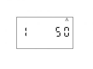
The fault code is displayed with OK. Explanations of most codes are present in the tables below.For some faults, the type of fault is also displayed in plain text. Acknowledging a fault Follow the instructions on the display.Example: Fault code “42”. In order to acknowledge fault press OK; the standard display will be shown once more.
The fault text will be displayed in the short menu. A tool displaying fault message, when connected, will be turned off. Whenever fault shown on display is not corrected, fault massage will be display again the next day and the fault message facility restarted. In order to call up acknowledged faults you need to press OK for minimum 4 seconds. Calling up fault codes history (up to 10 records, stored by date): press OK and menu buttons together for about 4 seconds. Choose “fault history” and then “display?”
Table 1 General fault finding table applicable for all Viessmann boilers
| Fault | Display | Solution |
| Control unit doesn’t issue a heat demand | No display | Increase set value and ensure heat is drawn off |
| Fan doesn’t start | F9 fault on display | Verify fan connecting cables and fan itself. Power at the fan and fan control |
| No ignition | EE fault on display | Verify the ignition module (control voltage 230 V), verify the gas supply pressure, verify the ionisation electrode adjustment and the gas line for airlocks |
| Burner not working | Burner stops below the set boiler water temperature and restarts immediately | Verify the flue gas system for tightness (flue gas re-circulation),verify the gas flow pressure |
| Burner blocked | F30, F38 on display | Verify the boiler water temperature sensor |
| Wrong calibration of the combustion controller | E3 or/and Eb fault on display | Ensure adequate heat transfer Press reset button. Verify the gap between ionization electrode and burner gauze assembly. Verify allocation of gas type (coding address 82, gas train setting). Verify flue system, remedy flue gas re-circulation if required. |
| Short circuit,outside temperature sensor faulty | F10, F18 on display | Verify the outside temperature sensor |
| Low loss header | F20, F28 on display | Verify the low loss header sensor |
| Mixer closes | F40, F44, F48, F4C on display | Verify the flow temperature sensor |
| No hot water | F50, F58 on display | Verify the cylinder temperature sensor |
| Control mode | F90, F91, F93 on display | Verify sensors 7, 10 on the solar control module. Verify temperature sensor at connection S3 to the Vitosolic 100 |
| No central heating | F92, F94 on display | Verify temperature sensor 5, 6 on the solar control moule or the Vitosolic sensor |
| Communication error,extension kit for heating circuit | Bb, bA fault on display | Verify extension kit connections and codes |
| Control mode without remote control | bC, bd, bE fault on display | Verify connections, lead, coding address “A0” and remote control settings |
Table 2. Viessmann boiler’s communication faults and example solutions
| Fault | Display | Solution |
| Communication fault | C1 on display | Verify electrical connections |
| Communication fault | C2 on display | Verify solar control module or Vitosolic |
| Communication fault | C3 on display | Verify electrical connections |
| Communication fault | C4 on display | Verify OpenTherm extension |
| Communication fault | C5 on display | Verify the setting of coding address “30” |
| Communication fault | C6 on display | Verify setting of coding address “E5” |
| Communication fault | C7 on display | Verify setting of coding address “E5” |
| Communication fault | C8 on display | Verify setting of coding address “E5” |
| Communication fault | Cd on display | Verify connections, Vitocom 100 and coding address “95” |
| Communication fault | CE on display | Verify connections and coding address “2E” |
| Communication fault | CF on display | Replace the LON communication module |
Table 3 Viessmann boiler’s control mode faults and example solutions
| Fault | Display | Solution |
| Control mode | d6 on display | Remove fault at the appliance concerned EA1- DE1 |
| Control mode | d7 on display | Remove fault at the appliance concerned EA1- DE2 |
| Control mode | d8 on display | Remove fault at the appliance concerned EA1- DE3 |
| Control mode | dA on display | Verify room temperature sensor heating circuit 1 |
| Control mode | db on display | Verify room temperature sensor heating circuit 2 |
| Control mode | dC on display | Verify room temperature sensor heating circuit 3 |
| Control mode | dd on display | Verify room temperature sensor for heating circuit 1 and remote control settings |
| Control mode | dE on display | Verify room temperature sensor for heating circuit 2 and remote control settings |
| Control mode | dF on display | Verify room temperature sensor for heating circuit 3 and remote control settings |
| Control mode | E0 | Verify connections and LON subscribers |
Table 4 Viessmann boiler’s burner related faults and example solutions
| Fault | Display | Solution |
| Burner fault | E1 on display | Verify gap between ionisation electrode and burner gauze assembly. In open flue mode, prevent very dusty conditions for the combustion air. Reset the appliance- press R |
| Burner fault | E2 on display | Ensure adequate circulation volume. Verify flow switch. Scaling, remove blockage. Reset the appliance- press R |
| Burner fault | E3 on display | Ensure adequate heat transfer.Reset the appliance- press R |
| Burner fault | E4 on display | Replace the control unit. Reset the appliance- press R |
| Burner fault | E5 on display | Replace the control unit. Reset the appliance- press R |
| Burner fault | E7 on display | Verify ionization electrode: the distance to burner gauze assembly, connecting lead and plug-in connections, contamination of electrode. Verify flue system, remedy flue gas re-circulation if required. Reset the appliance- press R |
| Burner fault | E8 on display | Verify gas supply (gas pressure and gas flow limiter), gas train and connecting lead. Verify allocation of gas type. Verify ionization electrode: the distance to burner gauze, the contamination of electrode. Reset the appliance- press R |
| Burner fault | EA on display | Verify flue system:remedy flue gas re-circulation if required. In open flue mode, prevent very dusty conditions for the combustion air. Reset the appliance- press R |
| Burner fault | Eb on display | Verify gap between ionization electrode and burner gauze assembly. Verify allocation of gas type page 13.Verify flue system, remedy flue gas re-circulation if required. Reset the appliance- press R |
| Burner fault | EC on display | Reset the appliance- press R Replace boiler coding card and press reset button once again |
| Burner fault | Ed on display | Replace the control unit |
Burner Operation Program Sequence
Often faults are wrongly described and therefore determine as issues with burner. Normal burner operation sequence is described below.
1. Stand by phase- it is complete shutdown until the next call for heat. In this phase both the combination gas valve and the blower are not receiving energy
2. Stand-still (blower test) phase. A call for heat will indicate the comminication to the blower. Stand-still position will be verified. Blower speed will be measured, and it needs to be < 300 rpm for a 70 second period
3. Pre-purge speed phase during which test Controller sends and receives signal to / from fan speed controller to verify maximum rpm of the blower
4. Pre-purge phase where pre-purge cycle starts within the pre-programmed timing. Pre-purge timing is in addition to previous phase. The fan speed must be greater than 1500 rpm.
5. Pre-ignition phase where ignition spark is initiated and controlled
6. Ignition phase / safety timing where we observe that the gas valve opens during the safety timing period (about 5 sec). If a flame is detected, this phase ends immediately in < 4.8 secs. If the flame is not established after 3 trials, the burner will lock out and will require a manual reset
7. Flame stabilization phase where controller required time for flame stabilization
8. Forced low-fire phase where controller will go into low-fire until required modulation signal (high-low) is processed
9. Burner normal operation phase. At the end of the flame stabilization period (5 sec.), a release for modulation occurs and the burner temperature controller will take over from the flame safeguard. Forced shutdown after 24 hours continuous operation
10. Post-purge speed test phase where gas valves are closed during this phase. End call for heat. Post-purge occurs during the programmed period. If the fixed high limit trips during normal operation, the blower will purge for 15-20 minutes to cool the heat exchanger.
11. Combination gas valve proof of closure test phase. If during the normal operation of the burner a controlled (or uncontrolled) shut-down occurs, a complete mechanical and electrical gas valve proof of closure test will be performed by the flame safeguard. After a successful mechanical and electrical proof of closure test, the flame safeguard will expect that the flame is not present. If, however, the flame existed for a period of >30 seconds, the flame safeguard will go into permanent lock-out.
Filling the heating system
Attention! Using not proper fill water will increase the amount of corrosion and deposits and will lead to boiler damage. Before filling system with new water you need to flush the whole heating system precisely. Use only the amount of water needed, no need for more. A hard water in excess of the following values:
a) single boiler systems and multi-boiler systems ≤ 200 kW: 11.2 °dH (2.0 mol/m3)
b) multi-boiler systems > 200 kW: 8.4 °dH (1.5 mol/m3)
need to be softened before getting into the system
In some instances antifreeze suitable for heating systems can be added to the fill water, however antifreezer should come from certified source. To refill the system follow the steps below
1. Verify on diaphragm expansion vessel the pre-charge pressure values
2. The valve that shut-off the gas showuld be closed
3. Fill the heating system via fill valve A and the boiler drain &. A minimum system pressure is > 1.0 bar
4. Close boiler drain & fill valve
Check diaphragm expansion tank and system pressure
Warning! Perform all verifications only when the system when cold
1. Drain system and reduce pressure until the manometer reading is “0”
2. If the nitrogen pressure of the pre-charged expansion tank is lower than the system static pressure, you will need to exceed the pressure system a bit. The static pressure required at the tank is based upon the static height of the system. The system fill pressure value must be equal to the expansion tank pressure value at approx. 60ºF (15.6ºC)
Attention! Static pressure of 1 bar (15 psig) is equal to static head of 33 ft. (10 m). It should be measured as a distance between topmost heat emitter and the boiler
3. Top up with water until filling pressure is higher than the inlet pressure of the diaphragm expansion tank
Attention! With the system cold, the filling pressure must be approx. 3 psig higher than the static pressure
- max. boiler operating pressure45 psig
- min. boiler operating pressure 14 to 23 psig
- relief pressure valve 30 psig
Value of the minimal filling pressure should be written down when starting up the system for the first time. Attention! You should pay special attention to low values at the manometer as they often show that there is a leakage in the system. If that is the case, then the leakage needs to be repaired before starting up the boiler.
Venting the boiler by flushing
To vent the boiler by flushing follow steps below
1. Close shut-off valves A and B.
2. Drain valve C should be connected to the drain hose. Boiler drain should be connected to the fill hose to and valve F (if no longer connected) as shown on the picture below
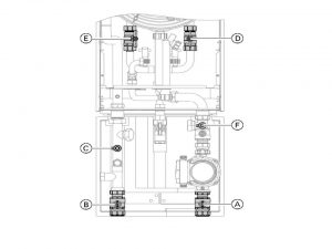
3. Close shut-off valve D.
4. Open valve F.
5. Vent the first indirect coil through shut-off valve E at mains pressure until no more air noise is audible.
6. Close shut-off valve E and open shut-off valve D.
7. Vent the second indirect coil through shut-off valve D at mains pressure until no more air noise is audible.
8. Close valves C and F. Open shut-off valve E.
Attention! Valves D and E must be re-opened to enable the boiler to operation.
Venting the heating system
Follow the steps below to properly vent the heating system
1. Valve shutting off the gas should be closed and control unit should be set to ON
2. Start venting program
3. Check the system pressure
4. Activating venting program for the units with weather-compensated control:
4a. Press OK and “menu” button together for about 4 s. Then go to- “Service functions” and then to “venting” OK
4b. To terminate venting program, press OK or menu buttons.
5. Activating venting program with for the units with constant temperature control:
5a. Press OK and menu together for about 4 seconds, confirm with OK. Whenever the venting program is started, “EL on” on the display is shown.
5b. To terminate the venting program press menu button
Checking the gas type
Table below includes gas flow pressure values in mbar and actions associated with the values per gas type
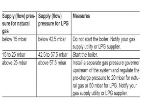
You can yourself check the gas type that is used or that should be used in your Viessmann boiler. Every boiler has a an electronic combustion controller. The purpose of this controller is to set/adjust the burner for optimumal combustion. All this need to happen in accordance with the proper gas quality. For boilers operating with NG no adjustment needed for the whole Wobbe index range. The NG Viessmann boilers can be operated in the Wobbe index range 9.5 to 15.2 kWh/m3 (34.2 to 54.7 MJ/m3).
In order to convert the burner for operation with LPG you will need to determine the gas type and Wobbe index. This information can be provided by either LPG supplier or simply gas supply utility. Then you will need to convert the burner for the operation with the LPG and finish with recording the gas type, most handy in the service report. To convert the burner you need to follow the steps below:
1. Set adjusting screw A on both gas trains to “2”.
2. Turn ON/OFF switch “8” ON.
3. Select the gas type in coding address “82”
- call the code 2
- call “general” for weather-compensated control units or group “1” for constant temperature control units
- inside of coding address “11”, select value “9”
- inside coding address “82”, select value “1” for LPG operation
- inside code “11” select value ≠ “9”.
- finish service functions
4. Open the gas shut-off valve.
5. Affix label “G 31” (included with the technical documentation) should be placed on the cap panel or near the gas train
Tightness of the balanced flue system verification
The requirement for a tightness test is being held the same for the wall mounted as well as for balanced flue systems. It is being done during commissioning by the flue gas inspector. It is recommended annually to carry out a simple leak/tightness test. The CO2 or O2 concentration tests will need to be carried out in the combustion air at the annular gap of the balanced flue pipe.
The flue pipe is deemed to be gas-tight if the CO2 concentration in the combustion air is either bigger than 20.6 % or lower than 0.2%. Whenever O2 values are lower and/or CO2 values are higher pressure test will be started. Test will run with the flue pipe with a 200 Pa pressure (static).
Frost protection function
Most Viessmann boiler models have built-in automatic frost protection function. This function allows the boiler to be shut off for an extended period of time while protecting it against freeze-up. Frost protection is non stop active function. The burner is turned on whenever temperature in the boiler is equal or lower than 5ºC. This function will switch itself off once temperature in boiler water gets close to 15ºC, and not more than 20ºC.
Repair work
Before starting any repair work on Viessmann boilers remember that components which fullfil a safety function can compromise the safe operation of existing heating system. Therefore replace bad components only with original Viessmann spare parts. Pay attention that the spare and wearing parts which have not been tested together with the heating system can damage or readjust its function. Installing non-authorized components and non-approved modifications/conversion (including software coding changes) can damage and readjust safety and may invalidate our warranty. For replacements, use only original spare parts from Viessmann or those which are approved by Viessmann.
In order to replace any parts of the Viessman boiler you will first need to gain general access.
1. Isolate the appliance
2. Loosen the screws at the bottom of the boiler as shown on the picture below, do not remove completely
3. Remove the front panel
4. After work on boiler is completed re-assemble in reverse order
PCB replacement
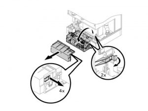
1. Isolate the appliance and gain general access
2. Push in the side locking tabs as shown on the picture below (1)
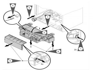
3. Pivot control unit forward (4)
4. Remove the cover (5)
5. Pull all plugs from the control unit (6)
6. Push in the side locking tabs and remove the pressure gauge from the control unit casing (7)
8. Undo both screws on the hinges and remove the control unit
9. Remove the control unit from the floor of the air box
10. Secure the new control unit with two screws on the floor of the air box
11. Fit the pressure gauge into the control unit casing
12. Connect all plugs to the control unit
13. Re-assemble in reverse order
Burner replacement
1. Isolate the appliance and gain general access
2. Replace electrical cables from fan motor A, mount burner, and diagonally tighten 4 Torx T-30 screws F to a torque of 4 Nm (35 lb.in.) as shown on the picture below
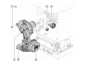
3. Insert new supplied gasket and tighten the fitting E on the gas connection pipe to a torque of 15 Nm (132 lb.in.)
4. Plug the Venturi extension D into the fan
5. Replace electrical cables from gas valve B, and electrode block C
6. Open gas shutoff valve and switch on power supply
7. Check the gas connection for tightness
8. Re-assemble in reverse order
Fuses replacement
a) Power pump module fuse
1. Switch off main power supply, isolate the appliance and gain general access
2. Check fuse F1 T6.3A as described on the picture below. Replacements fuses part number 7815 580.
3. Reassemble in reverse order
Attention! Breaker or main service switch must be turned off because the on/off boiler switch has no ability of disconnecting power to the boiler or/and pump module.
b) Control unit fuse
1. Switch off main power supply, isolate the appliance and gain general access
2. Flip down control unit
3. Remove cover
4. Check fuse F4 T 2.5A Replacements fuses part number 7404 396
5. Reassemble in reverse order
Flow limiter replacement
1.Switch off main power supply, isolate the appliance and gain general access
2.Drain the boiler and combiPLUS
3 Undo screws A as shown on the picture below
4. Remove the cap B. and the faulty flow limiter C.
6. Select new flow limiter C corresponding to boiler size
7. Insert new flow regulator C.
8. Fit new cap B provided
9. Re-assemble in reverse order
The plate type heat exchanger replacement
1.Switch off main power supply, isolate the appliance and gain general access
2. Drain the boiler on the heating water and the DHW side
3. Disconnect diverting valve motor connection
4. Push the three-way drive A slightly upwards
5. Turn the three-way valve B with drive A 1/8 turn counterclockwise and remove as shown on the picture below
6. Remove two screws C from the plate-type heat exchanger and remove the plate-type heat exchanger D with gaskets
Attention: While removing small amounts of water may trickle out and escape from the removed plate- type heat exchanger
7. Verify the DHW side for scaling and if required, clean or replace the plate-type heat exchanger
8. Verify the heating water side for contamination and if required, clean or replace the plate-type heat exchanger
9. Re-assemble in reverse order with new gaskets
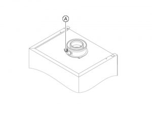
Flue gas temperature sensor replacement
1.Switch off main power supply, isolate the appliance and gain general access
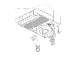
2. Pull the leads from flue gas temperature sensor A as shown on the picture below
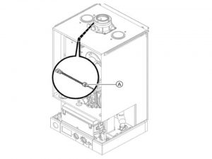
3. Check the sensor resistance
4. Replace the sensor
5. Re-assemble in reverse order
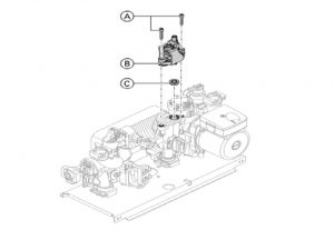
Fixed high limit replacement
1.Switch off main power supply, isolate the appliance and gain general access
2. Pull the leads from fixed high limit A as shown on the picture
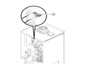
3. Verify the continuity of the fixed high limit with a multimeter
4. Remove faulty fixed high limit
5. Coat the replacement fixed high limit with heat conducting paste and install
6.Re-assemble in reverse order
7. Reset your boiler
Attention! Verifying Fixed high limit functionality should be done in each instance when burner unit control cannot be restarted after a shutdown because of fault repair. this includes the instances when the water boiler is below 95°C.
Outdoor temperature sensor replacement
1.Switch off main power supply, isolate the appliance and gain general access
2. Disconnect cables from outdoor sensor
3. Measure resistance of the outdoor sensor and compare with resistance / outdoor sensor curve
4. If the value measured differs significantly from the standard, replace the sensor
5. Re-assemble in reverse order
Attention! In the optional weather-compensated mode the boiler water temperature is regulated to the outside temperature
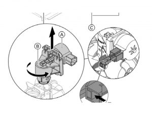
Boiler temperature sensor replacement
1.Switch off main power supply, isolate the appliance and gain general access
2. Disconnect cables from boiler temperature sensor A as shown on the picture below
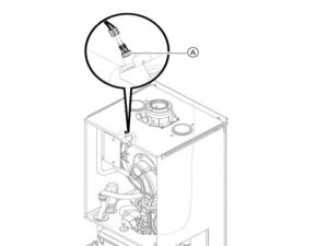
3. Measure resistance of the boiler temperature sensor and compare with resistance/boiler water temperature standard curve shown
4. If the value measured differs significantly, replace the sensor
5. Re-assemble in reverse order
Warning!!! Before putting our boiler back to the operation remember to always verify the gas smell around the whole area where boiler is located and gas pipes are settled. When checking the gas smell you need to verify it on two levels: normal (head) level and then floor level because gas is much heavier than the air, and the fact that you feel nothing or not much at the head level doesn’t mean that the gas is not commulating at the floor level. If you smell the gas:
- don’t try to light any appliance (not only boiler but any electrical or gas appliance)
- don’t touch any electric switch
- don’t use any phone in your building
- call your gas supplier from a neighbor’s phone immidiately and then follow the gas supplier’s instructions.
- in instances when you cannot reach your gas supplier, call the fire department
- when turning the gas know you should be using only one of your hands, using any tools for this purpose is prohibited. In instances when knob turn into the right position, you shouldn’t attempt to fix it, contact your boiler specialist. If you try to force it or repair it yourself you accept the risk of explosion or rapid fire
- don’t use this appliance if any part has been under water. Immediately call a qualified boiler specialist in order to perform checks on your appliance and/or replace parts that were under water